

NE0
-
Posts
675 -
Joined
-
Last visited
-
Days Won
39
Content Type
Profiles
Forums
Gallery
Events
Yamaha Racing News.
Media Demo
Store
Collections
Classifieds
Posts posted by NE0
-
-
VHT is readily available here so that might be the option.
I purchased some XHT(Xtremely High Temperature) from ebay made by auto inparts.com a few weeks ago for my Honda engine. Putting it on tomorrow in the sun, but can't tell you how good it will be as i've never used it before.
Previously on my Honda I used Eastwoods engine paint, which was the dogs danglies, sadly no longer available (I've checked with eastwoods USA and its been withdrawn........it did state on the can known to cause cancer!!!) but it stayed nice for 20years!!!
-
Not one of your better finds there drewpy.............
-
The ignition switch block diagram part comes from the circuit diagram printed in the Haynes manual.
I've cut out all the chaff and simplified the rest for clarity.
It shows the internal configuaration of the switch. There are other diagrams which shows the internal arrangements of the handlebar switches and the larger diagram (above) even shows the plug connections.
I've looked at the circuit diagram for the US models DT125 and DT175 F G and H models and whilst the main switch on these machines doesn't have position1, the circuit on position 2 is identical to their diagrams.
ie the rectifier, regulator and headlight are all connected to the same principle above.
as I once said to a grateful friend I might not have a degree or diploma......... but I can read a circuit diagram!
-
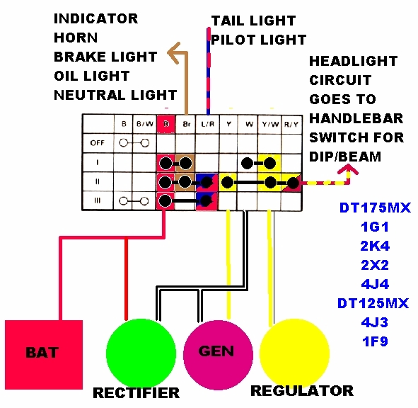
Here's the simplified circuit diagram showing the connections via the ignition switch (colours corrected)

the ignition switch positions
1 = Engine RUN. Indicator, horn, brakelight active powered by the Battery.
Gen charges battery via Rectifier white wire. White wire connects to the Regulator which prevents Battery Frying!
2 = Engine RUN Indicator, horn brakelight active. taillight and Pilot ON. Powered by the Battery.
Gen white wire continues to charge Battery but is disconnected from the Regulator,
Plus Headlight circuit now active either dip or beam. Powered by the lighting coil in the Generator. Regulator Switched to Prevent bulbs blowing!
3= Engine OFF. tailight/pilot light ON (For Night parking)
This is for the UK models listed.
I will check the US circuit diagrams but its unlikely to be so different!
You will notice how the REGULATOR and RECTIFIER are wired and involved in the circuits whether the lights are ON or OFF.
-
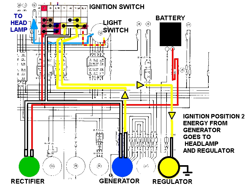
Ok back from work and I've done this for the MX taken from the circuit diagram,
I know i may have used the WRONG colours but you need to see where the wires go
This is the circuit used when the IGNITION is on POSITION 2
Within the ignition switch, brass parts internally connect the separate circuits to function as ONE.
If you take voltage readings for individual wires disconnected from this complete circuit you're reading will not reflect the end voltage. ie taking a voltage reading on the yellow wire in the headlight shell on its own the volts will be over 15volts at higher revs,
Not the best choice of colours I admit BUT does this help you understand whats connected?
Because to say "I really don't believe the voltage regulator is part of the headlight coil / circuit " without access to a circuit diagram is not the smartest statement I've read !
Regardless of it being USA your bike will not be dissimilar . Our haynes manuals has US diagrams.
-
I'm off to work now and can't reply in much detail at the moment, but suffice to say...
You really need to get hold of a circuit diagram!
Remember, on a stock bike with everything connected I'd get 6v at the headlamp!... to run the 6v light bulb...... otherwise it would blow!
If I DISCONNECT the regulator and rectifier and take the voltage at the headlamp I'd get the voltages listed in Part3 The lighting coil
Let there be light….
Remember also the c90 regulator/rectifier is a combined unit and replaces BOTH of the disconnected Regulator and Rectifier mention in the text.
I'll post some circuit diagrams to explain further when I'm home , until then off to work...................going to be late now!
-
Here in UK and probably Europe, we have single Pilot bulbs, or parking bulbs INSIDE the headlamp shell.
They are small bulbs; larger than the dash bulbs but smaller than an indicator bulb. Rated about 10w.
The ignition switch enables the tail light and parking 'headlight' to be ON with the key removed.
I guess so other road users can see the 'parked' vehicle. Not really aimed at being left on for too long otherwise it will drain the battery. Often its part of the tail-light circuit.
-
Hi oisact,
Wecome to the club, normally we ask that you post in the new members section before we give out a detailed reply. its forum etiquette. You can still do that and you'd be very welcome.
On the other hand Glad to see this now old thread is still helping people.
I've read through your two posts and i think you've answered your own questions but nonetheless I'll still reply........
Well done for moving over to LEDs, it's not something I did. I assume they have bulb holder bases? or do they need to be modified?
you say that according to the wiring diagram, your headlight is connected to the battery.I never stated the headlight was.
The conversion is the 12v battery runs the tail-light, indicators,brake lamp, dashbulbs and horn.
The charging coil.......charges the battery.
The lighting coil runs the headlight ONLY.
In Part6 it states
The Main headlight will now run off the generator. The rest of the lights and horn will, as before, run off the battery. Only this time it’s 12volt.Re reading my own posts you might be referring to the earlier post Part3b the regulator where I mentioned
The tail light and pilot/headlight are both on drawing current from the battery
The bulb I'm referring to is the Pilot in the headlight! or the parking bulb in USA???
I'll amend the sentence.
The British Ignition switch, allows the bike to run (position1) charging the battery, with the headlight OFF.
In postion 2, the Battery continues to be charged but ALL the lights mentioned above are ON from the battery and the headlight bulb is ON powered by the lighting coil.
The regulator is SWITCHED in the British ignition switch.
In position 1 on the ignition switch, (engine run on lights off) the white wire from the generator goes to the switch and is connected to the yellow/white wire to the regulator. In essence soaking up the excess volts which would fry the battery.In position 2 (engine run, lights on) the yellow wire from the generator is switched to the yellow/white wire to the regulator.
In postion 2 the white wire is disconnected
Yes you're right a circuit diagram IS and would be very useful for you.
The 12v 35W headlight is dim at low engine revs in this conversion. At tick over the light glows orange.
But you don't ride along the highway on tick over!
Once moving along the highway, revs above 3000 will make the bulb brighter.
The coil outputs are correct for my bike, others in other countries have been just as succesful, your coil MAY not be the same.
BUT if you're getting 20v at 6000revs then you are getting more than I do on the lighting coil. so i see no reason why it would not work.
On a later update I also mentioned I upgraded the headlight bulb to 12v 45W and the bulb is a lot brighter than the 35w one BUT it still glows orange at low revs but is noticably brighter than the 35w one.
This I'm afraid is a problem......a 12v bulb is an INCANDESCENT bulb and has a filament which glows and gets brighter depending on the power going through it.
Plus all my results are based on the fact I'm using the C90 regulator, which one are you using to get your results? you don't mention it. If you're testing with original 6v one then you won't get the same results.
i.e what voltage you are producing will be clipped down to 6v regardless of how much the bulb wants!
-
I think its fair to say he's a breast man!
-
I used Q20 last winter and although expensive, I think it was the dogs dangly bits!
I know I've posted this before but just check out this sales video!!!....... although don't try it at home!
-
Glad to have been of service.
-
OR
If you go to ebay and type in microfiche scanner there is a service there which can convert you fiches to CD, won't be free ok course!
Done my bit!
-
Yes the ol USB microscope is amazing, you can see all sorts of things close up and on the big screen, not expensive under £20 a few years ago. Also got a USB Endoscope which you can put under the floorboards to see where things are prior to lifting the boards, plus comes in handy checking in accesible parts on the bikes and cars!
-
http://howtoscan.ca/natural-negative-scan.html
I've played around with my scanner settings this morning but the maximum I can get is 1200dpi whereas the link above shows his software capable of up to 4000dpi.
I tried at 300,600, and 1200 and each scan it got better and better with more detail but i can't go any higher. I'm sure if you can you would solve your problem.
-
There is a couple of ways which may help.
You could try scanning the microfiche with your PC scanner
I found my DTMX microfiche and did this with my canon MP610 (Printer/Scanner all in one) its quite old now, but it has the ability to scan at 1200 dpi, more modern scanners can probably do better, i cropped the scan, I know you cant read it but its nearly there, Like i say a newer scanner might do better.
Alternatively, you could try a usb microscope,....................... good old ebay!
here it is on my DTMX microfiche and the result below filled the screen it was in focus before I pressed the capture button!!
Plus a closer pic held about a 1mm above the fiche. This picture below filled the entire screen in this clarity
If you go down this route it took me half an hour just to produce one photo!! too bloody fiddly! but it worked.
-
I do recall a few years ago having been cut up, pulling along side someone (possibly in a BMW!) and politlely saying:
"Excuse me, mate, your indicators don't work"
He duly, flicked the stalk up and on went the indicator tell-tale on the dash, saying ...yeah they do!
" Well FUCKING use them!!!" was my reply. As i drove off into the distance!!!
TWAT!
-
I might be pissing in the wind here, but as they say its far better to be on the train pissing out, than it is to be on the platform trying to piss in!
Fortunately the number of yamahas upto 1967 was finite!, there's not a lot of choice.
U prefix may have been the U5 scooter 1966 to 1968 or yamaha Newport 80cc Available in the US.
This shows a nicely restored blue one in the USA
http://www.flickr.co...in/photostream/
These video shows a close up of the engine casing number on this 1967 model as something then 26 and numbers not disimilar to 26-four numbers.
if the bike was wrecked the engine casing may have been where they got the number from??
-
I had a quick look on ebay-uk folks and DT's PERMATEX is readily available here in black as he suggests.
No DT, I got a feeling I didn't, I know I was thinking about it, but for whatever reason I never did, paid for it in the end as it's leaked oil in the same place for years, just a dribble but more recently on a long run it gave up the ghost and started pissing out! which is where "blown a gasket" comes from!!!Did you re torque after first warm up?Not something i'm going to miss doing this time though!
Initially I'm going to reuse the old rocker cover gasket, then after a few miles re-torque the head and then replace the old gasket with the new one.
-
I did a search through the forum, nobody seems to have asked this question before, or if they did, they put it in title with a cryptic heading like "help" or "question" or "need help" that sort of thing, I must confess these simple titles get my goat up!!! why can't they be more concise?
Anyway back to the question in hand.........
I'm just in the process of doing an engine rebulid on my Honda CB400/4 , I did the DTMX 175 last year!!
The base gasket has leaked oil for some years, in fact shortly after i rebuilt the engine a few years ago it started...but recently its got worse and enoughs enough! i decided its time to fix it, so engine out and replace the seals and the gaskets, and whilst I'm in there I'll do the primary and cam chain (£80 for the primary chain!!!!.........'kin hell!!) I didn't replace the primary the first time around just did the shell bearings, rings and cam chain. false economy i know it was probably a lot cheaper then too!.Mind you next to no wear on the shells which i'm pleased with.
However, I'm just in the process of putting it all back together, and I thought what do others do when it comes to fitting the gaskets.
Back in the 70's and 80's it seemed to be common practice (in my neck of the woods) to smear the new gaskets with a thin layer of instant gasket (except for the head) just for insurance purposes, i.e make sure the bugg'r don't leak!!
When i rebuilt the DT175, I must confess I put a thin film of hylomar blue on the crankcase halves along with the gasket, it didn't do it any harm, made a barely visible blue line (there wasn't so much that it made large globules of the stuff inside and out! that could have resulted in foreign matter in the workings). it doesn't leak.
I recall back in the 70's and 80's old cortinas and the like with bright orange silicone in big unsightly globules all around the joint faces....they also didn't leak but looked sh*t!!
What are your thoughts and recommendations fellas,
Put them in dry?
Use a thin film of instant gasket?
Smear them with oil? smear them with butter, jam......... body fluids!
or maybe Leave them out altogether?
(that last one was a joke!!)
-
My advice would be to stop trying to fix it piece meal and simply take the whole engine out, strip and restore it, that way you can renew all the bearings, seals, gaskets etc. its a simple motor, will take you less than 2 hours to strip it down completly (taking digital photos as you go).
Its not expensive to do and that way you'll know everything is done and will last for a few more years, i did mine last year and its been perfect since.
in the time you've been trying to sort it , you could have put it back together and it's not as if you've been relying on it to go to and fro from work as it doesn't go now!......go on, bite the bullet and take it out!
-
on another note. At 33 years, are the copyrights for the Yamaha manuals not expired? Seems like they should be in the public domain by now
What makes you think that?
Before using original material, you needed to obtain permission...............Having been the editor of a car club magazine for 7 years, there was a bit about copyright which one had to be aware before using it or making it public!
Literary, Dramatic or Artistic Works
Copyright lasts for 70 years after the year of a known author's death. For unknown authors it expires 70 years from the end of the calendar year in which the work was first made available to the public. If a work is produced by two or more authors then the copyright lasts for 70 years after the death of the last of the authors to die.
Which manuals are you referring to?
The Haynes type manual? then Haynes being the publisher and author will not be giving it up as they still publish the books.
If you mean the Yamaha manuals by Yamaha for use by Motorcycle dealers/repairs, even though its no longer published, then the above will still apply from the date it was copyrighted/first published on the inside cover.
You'd have to ask Yamaha to make it public, but its highly unlikely to make it to any meeting as an agenda item, it will not be a priority at all......making money will be on the agenda along with performance and the like!
Regretfully Copyright is not open to public debate or your own interpretation of it, or your own understanding of it, or how you can justify using it.
It's a law, of which if you break it, and a client wants to take it further, you will lose.
Lawyers making a living out of this sort of thing!!!..........on behalf of the client who is agrieved of course!!
-
Would it be part 25 and part 27, scoop air bracket and rubber damper.
http://www.cmsnl.com/yamaha-fzr600-rh-1996_model10286/partslist/C-12.html#results
Part No OEM number: 3HE-2137W-00
and damper OEM number: 3HE-2139U-00
certainly looks like it to me
next time.......do a little intro in the newbie area, and try and mention the bike you want help with in any title
-
I've no idea either, but i'd wish you had made title a little less cryptic!!
Please help identify part on FZR600 instead of just please help!!!
-
Got sent this, sure some of you have to, however, i thought I'd share it here.......very amusing!
Baldrick: "What I want to know, Sir, is, before there was a Euro there were lots of different types of money that different people used. And now there's only one type of money that the foreign people use. And what I want to know is, how did we get from one state of affairs to the other state of affairs."
Blackadder: "Baldrick. Do you mean, how did the Euro start?"
Baldrick: "Yes, Sir."
Blackadder: "Well, you see Baldrick, back in the 1980s there were many different countries all running their own finances and using different types of money. On one side you had the major economies of France , Belgium , Holland and Germany , and on the other, the weaker nations of Spain , Greece , Ireland , Italy and Portugal . They got together and decided that it would be much easier for everyone if they could all use the same money, have one Central Bank, and belong to one large club where everyone would be happy. This meant that there could never be a situation whereby financial meltdown would lead to social unrest, wars and crises."
Baldrick: "But this is sort of a crisis, isn't it Sir?"
Blackadder: "That's right Baldrick. You see, there was only one slight flaw with the plan."
Baldrick: "What was that then, Sir?"
Blackadder: "It was BOLLOCKS!."


Can you shed some light on a bulb question?
in Yamaha Workshop
Posted
heres a quick answer then.....
If its a 6v bulb with two figures afterwards....each one represents the watts of the two filaments inside. One is 17w and the other 5.3w
you have a rear light bulb which has a brake light inside too..........
hopefully I haven't turned you on too much!