

DE51GNZ
-
Posts
24 -
Joined
-
Last visited
-
Days Won
1
Content Type
Profiles
Forums
Gallery
Events
Yamaha Racing News.
Media Demo
Store
Collections
Classifieds
Posts posted by DE51GNZ
-
-
Hi Guys,
Just a quick post to say i have found a really good site that has online motorbike and ATV manuals.
The site has full colour photos of each step of any job you want to do to your bike.
I have my XV 125 and have just recently done new clutch and steering bearings and it has been a lifesaver.
The site is: CYCLEPEDIA check out the following link: http://www.cyclepedia.com/
The complete list of manuals available is here: http://www.cyclepedi...online-manuals/
The cost is good too.
I paid $24.95 for a 1 year access for the XV 250 manual (which is almost the same as my XV 125)
You only have to pay $42.92 for a lifetime access to the manual. Thats about £28 for a lifetime!!!!!
Not sure if you guys are interested but if you need something more than a Haynes manual then check it out.
I find it really useful and it has already saved me a fortune.
Regards
Dan
-
Hi Jimmy,
I dont seem to have a problem getting parts. I get them from:
They have a great service and parts are well priced.
Do you have a parts list for the bike? If not send me your email and i will send it over for you.
Regards
Dan
-
I have a xv125 can some one help with all the pipe connections?
3 connections on the tap top middle and bottom plus the pipe off the inlet and the pipe back off the pump
I also have a pipe connector missing a pipe on the carb
Help
Help
Cheers
Beefy
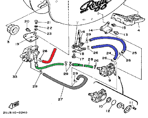
Hi Beefy,
I am with you on this one, when i first got my Xv 125 i had the same problem, so here goes!!!
The image below shows the parts diagram and i have colour coded the pipes to help.

OK 2 dark blue pipes come from fuel tank and go to the top 2 inlets on the fuel tap.
Grey pipe goes from bottom of fuel tap to the side of the fuel pump. Second one down.
Red pipe goes from fuel pump to carb.
Green pipe goes from left of fuel tap and joins T piece which then goes to bottom of fuel pump and manifold. This is the Vacum pipe.
Here are a few photos of mine. hope they help.
I think that just about ocvers it but if you need any other help just let me know.
Also do you have copies of the XV 250 service manual and XV parts catalogue. If you dont then email me andd i will send them over to you, they helped me a lot.
Thing to remember is your not alone. We are here to help if you need it.
Regards
-
 1
1
-
-
Hi,
Thanks for all your help.
I have moved the indicators and added new wires, all fitted now.
Thanks again.
I love this site!!!
-
Hi Guys,
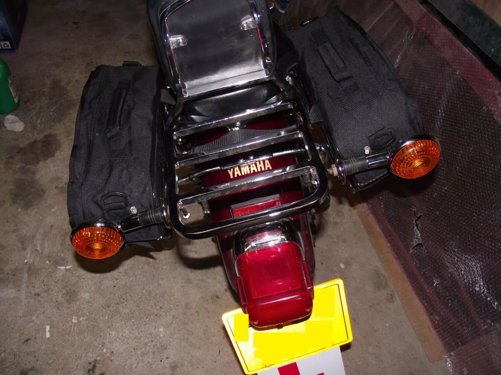
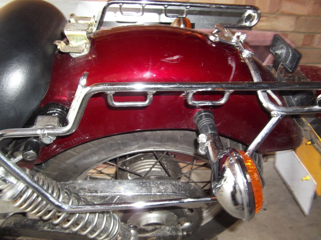
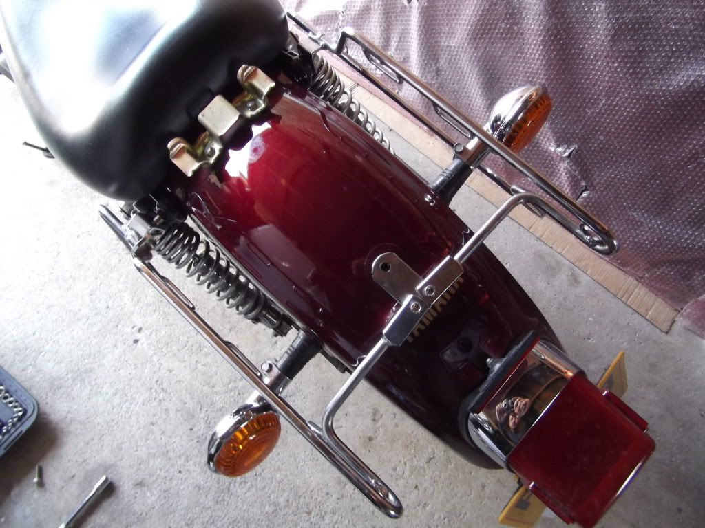
I recently purchased a set of XV 125 pannier racks from Ebay, these are the genuine article, but they have no fitting instructions so i am lost as to how they fix.
I think i may have worked out that they bolt through the mudguard and then the pillion seat but if i place them, the holes line up but the indicators are in the way.
It seems that in order to use them that the indicators need to be moved.
Anyone out there got similar and can light the way?
I dont mind moving the indicators to further around the mudguard, but this does mean i will need to extend the wiring as well. My only issue is, i must be missing something!!!
Any help would be appreciated.
-
Hi,
Check out page 96 (section 3-20) of the XV250 service manual for the instructions.
Regards
Dan
-
Hi,
I have the same bike and i get all my parts from
the part numbers for the bolts are:
1 x Long one- 98501-06090-00
2 x Short - 98511-06025-00
Give the parts department the part numbers and they can send them out.
I have a complete parts list for the XV250 (practically the same bike) if you need a copy
Regards
Dan
-
Thanks guys,
I adjusted the gear arm and now it seems great.
I can get all gears smoothly.
Thanks for your help and advice.
It is always appreciated.
-
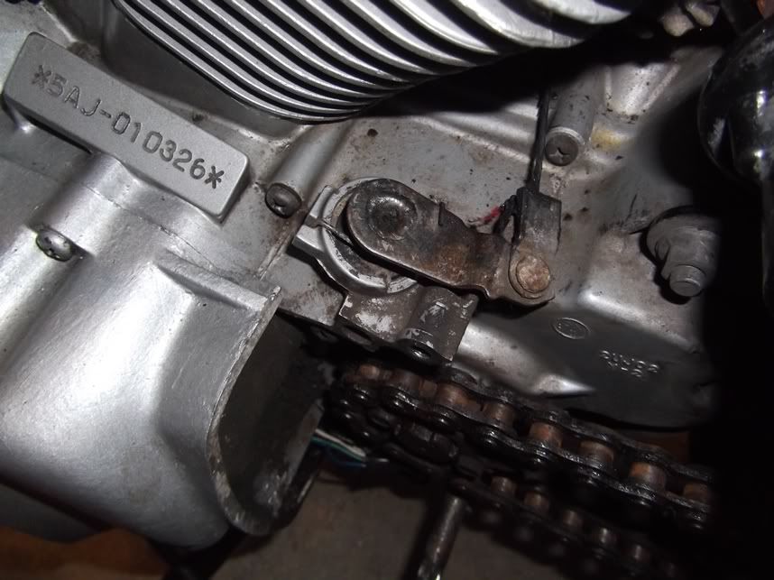
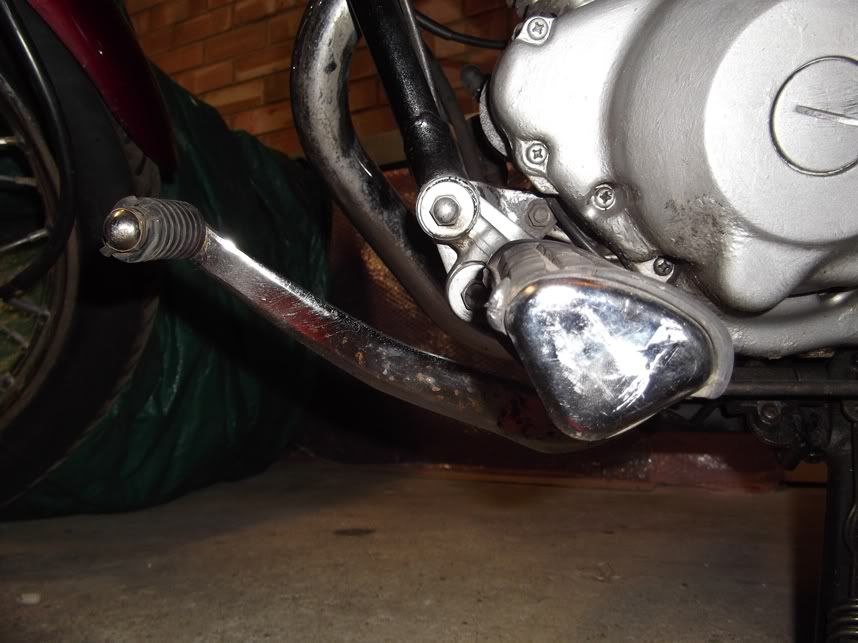
Hi Guys,
I noticed that the clutch cable on my bike was getting a bit old so i decided to replace it with a new one.
I have replaced it and adjusted it to the XV 250 manual settings. i.e 3-5mm play on the clutch lever.
Can anyone confirm that the position of the clutch mechanisum looks ok?
I am assuming that the arrow on the bottom of the arm is supposed to be in line with the gearbox casing.
Also can anyone give me some guidance on the lever arm?
When you look at the stem from the gearbox it has a mark on it.
I again assume that this is to line up with the gap in the gear lever arm?
If this is the case then according to the service manual both connections should be at 90 degrees to the main arm.
Mine seems to be right if this is the case.
According to the manual the height between the top of the foot rest and the top of the gear lever should be within 30-36mm. Mine seems to be at around 20mm.
This would mean that i would need to adjust the arm to make the lever go up.
Question i would like to ask is, does this fit with everyone else or should i just move the connection to the stem around so the lever is high enough?
I hope you guys can help.
I do trust the manual but in my lack of experience i value your option more!!!
-
Hi dan thanks for the reply.
I have the 125 not 250. I am watching a service manual on ebay, as i dont have one and i intend to go to maplins to grab a multimeter today.
how i do no when i have reached 5,000 revs? no techometer
Hi,
I dont have a tacho either but i just give it some revs and the voltage should go up. I guessed at this as the engine idling speed is around 1250 -1350 rpm. So i just guessed at twice the revs.
Send me your email and i will send over the service manual to you.
I have a XV 125 but other than the engine size the frame and electrical section are exaclty the same. I used the XV250 service manual to fix my bike. it really helps.
I'm not sure there ever was an official XV 125 service manual made by Yamaha?
Regards
Daniel
-
Hi all, hope you are well.
I am an all-weather rider, and have been used to riding with headlight on no matter what, but a couple of months ago bike rugularly struggled to start while headlights switch was on...after switching all electrics off and trying again it would find it easier to start but still not how it used to be. i had a new battery put on may 2010.
a week ago, i noticed that when i was stationary at a junction ticking over with indicator on, it would play havvock not flashing in time and going mega fast. Strange?!
THEN 2 days ago 16 miles from home with a full tank while riding she was slowing down, revs the lot. after pulling over i managed to keep her going for 30secs then cut out, not even ignition - or power for the horn! (leaving me to push her up a rather nice hill
)called AA, i insisted on a motorbike van, but they were tied up in london and i was in Wing, near stewkley! so i got an old boy kitted out for a car. After waiting 3 hours id already taken battery panel off.
He turned up, connected jump pack, and wahhhey! Ignition and started 1st time. Waiting 10mins, took off n she cut out. hmmmm.
using a volt meter saw only 6 going thru it without jump pack. i then got recovered to home.
surely this would be a charging problem? Yesterday i bought new battery n fitted it. Works fine, but i want peace of mind that there isnt a charging prob. my garage have said that without a volt meter i could try starting engine keeping ticking over, headlights on and as i rev headlight will appear brighter if bike is charging battery. to be honest, in my opinion nothing changed.
Does anyone have any advice or been through this? if i buy a volt meter im presuming that it should be 12 after starting and 12 before? would that prove everything ok?
Many Thanks,
Tom
Hi Tom,
Do you have a copy of the XV 250 service manual. If not email me and i will send a copy over. On page 251 it shows how to test the charging system.
I test mine with a simple multimeter, Set multimeter to DC20V and then rev the bike to 5,000, the multimeter should show 14-15V if the charging unit is working ok.
Regards
Dan
-
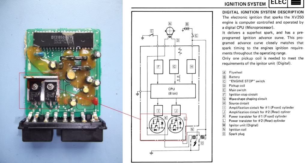
Hi Guys,
I have recently had problems with my XV 125 and through the help of this forum and a lot of testing with a multimeter i have finally solved my issue.
Turns out that the CDI unit was faulty and i have repaired it now and i thought it would be a good idea to get it up on the forum for future use.
The problem i had was that only 1 cylinder was firing. I only had the front cylinder firing on my bike.
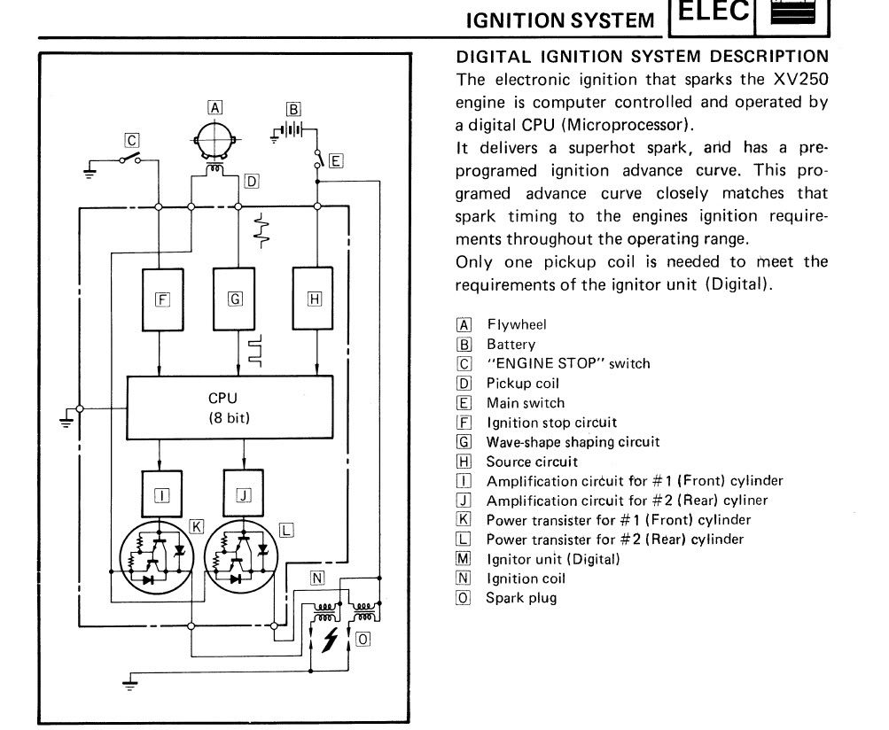
I did the usual, checked plugs, checked coils and all seemed ok. So from there i worked from the Iginition electrical diagram
If you look on the diagram the command to fire comes from a number of factors:
A = Primary pick up coil
B = Battery
C = Side Stand Switch
E = Main ignition switch
Now remember my bike was only firing on 1 cylinder. So from the diagram i could tell that the side switch was working ok, igintion was fine and the bike only has 1 pick up coil, so if the CDI unit was getting the message to fire then both cylinders should get it.
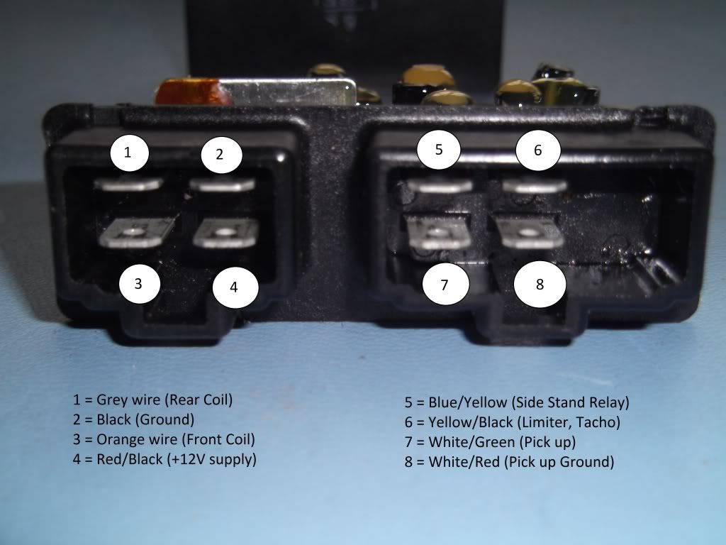
My rear cylinder was not firing so from the tracing of wiring using the XV 250 service manual i was able to work out the key for each of the connectors for the CDI unit.
Now the front cylinder is fed via the orange wire and the grey feeds the rear cylinder.
Just to check i swapped the orange and grey wires on the coils and then it begain to fire. So i knew that the CDI unit was not sending the fire signal to the second coil via the grey wire.
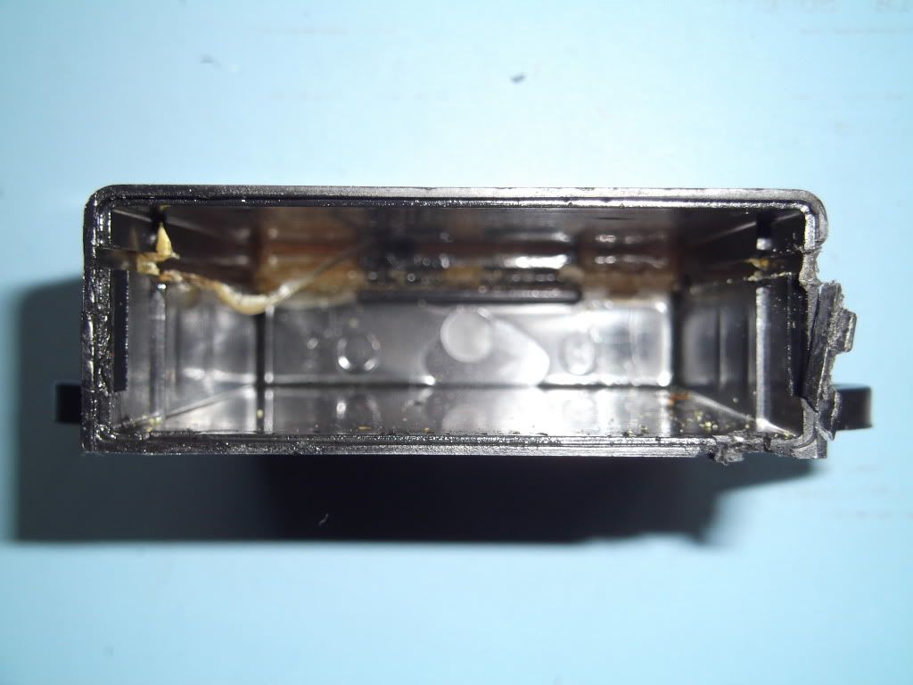
Time to open up the CDI unit!!!
Now opening the unit is not an easy task, the whole board slides into the case and is glued in place during manufacture. So getting this out was not easy but with some (convincing!!) it finally came out.
I now have the CDI circuit board out of the case.
As you can see there is not a lot of components to a CDI unit. (which begs the question why does Yamaha want £450 for a new one!!!)
In the electrical diagram components J and K are the power transisters that send the charge to the coils.
With a short electrical test on these transisters i found that one was not working. In the picture the left hand transister feeds the orange (front) coil and the right hand one feeds the Grey (rear) coil.
It was the right hand transister that was not working. This unit as a 2SD2141 Avalance Diode. See datasheet http://www.classiccmp.org/rtellason/transdata/2sd2141.pdf
This diode is the ignitor, driver for the circuit. So i needed to replace this unit. I managed to find one from a company in Surrey called littlediode.com http://www.littlediode.com/components/search.php?mode=search&simple_search=Y&posted_data%5Bby_title%5D=Y&posted_data%5Bby_shortdescr%5D=Y&posted_data%5Bby_fulldescr%5D=Y&posted_data%5Bby_sku%5D=Y&posted_data%5Bincluding%5D=all&substring=2SD2141&search_redirect=Y
This cost £6.99 with additional £3.00 for first class postage.
Soldered the new unit in, tested and then put the unit back together again. (did have to removed glue from circuit board on edge and from case)
Got it back together, put back on the bike and hooray!!!!!!
Now have bike firing on both cylinders!!!!
So my advice is, before you think about replacing your CDI / TCI unit, take a look inside. You never know you maybe able to fix it!!!
Some websites i found refer to the unit as a TCI and some as a CDI. For more info on this check out this great website http://www.jetav8r.com/Vision/IgnitionFAQ.html
Helped me a lot.
My information here is based on my personal experience with the specific problem i had with my bike. Not sure how it may help if you have other symptoms but i thought it would be useful to put up on the forum for future reference.
Any questions please let me know.
Hope it helps
Dan
-
2
-
-
Bro please it would be helpful for me as well as the community if you could graphically show where was the fault and how u fixed it, I mean detecting the faulty diode, how u opened the CDI unit...etc..I hope u could open it up once again for us..that sort of issue can come up for any of us XV125 users so please share it in detail..
Thanx..
Hi Kelum,
I will post full detail with photos up today as a new topic.
Regards
Dan
-
i dont know how to check with a voltmeter im afraid all i know is to hook it up to the coil and do a visual check on the plug.
you could try hooking the volt meter up to the good side and see what sort of readings you get
then use that as a basic for the broken side.
what i do know is that its not the actual stator that sends the signal its a pulse coil which is located in the left side engine casing... if you can find the plug that connects engine to loom there will be 3 wires(all the same colour either white or yellow normally) there the ones from the stator, then on the same plug should be a red and a black (or earth) then you should be able to see another set of wires (not sure on colour but should be 2 of them) there the pulse coil wires that send the signal to the cdi
i can send you a xvs 125 dragstar manual via e-mail both the virago and the dragstar use the same engine (with minor alterations) which might be helpfull
but if one side isnt firing and the coil is ok id check that you havent got a broken wire somewhere in the loom. or a loose connector.
the cdi is a sealed unit and there is no way of checking it im afraid other than to "borrow" a working one to swap and try.
to be honest i think that will be the simplest idea, then if the "borrowed" cdi dont work you know its the connection from cdi to coil.
Hi Guys,
Update on the bike.
Checked the primary coil and cleaned it but the bike was still firing on one cylinder.
It was the CDI unit that was faulty, not sending a singal on the grey wire.
Opened the CDI unit up and did some checks, turns out one of the Avalanche diodes had died.
Ordered a new diode from littlediode.com for £6.99, soldered in an now the bike has sprung into life!!!!!!!!
So CDI fixed and bike running sweet!!!!
Thanks for all your help.
-
Hm...guess u've located the issue...piston rings for this model are available on ebay..I saw several on offer...keep them checked also as it will be advisable...
Hi guys,
I have checked the compression on the cyclinder and it is all ok. I tried your trick paul and it nearly blew my thumb off!!
I checked the spark with a tester and NO SPARK.
I thought i had better check that it wasnt the coil, so i swapped the orange and grey wires around and then it sparked. So both coils are good.
It seems to be the signal from the CDI unit. The grey and orange wires come from the CDI unit. Continuity all good from CDI connector to coil.
So back to point 1...
Does anyone think it could be the CDI unit? Is there a way of testing that it is sending a signal with a multimeter?
Could it be the pickups on the stator windings not sending the signal to the CDI?
Any ideas on what to try next?
-
yeah id agree with kelum on this one check that the plugs are sparking.
then put ur thumb over the spark plug hole (to seal it) then push the start switch...your thumb should be pushed off and air should escape through the hole. the idea is to check compression you should be able to push against it as hard as you can but air will still push ur thumb and escape. if you find that there is little to no pressure then im afraid its ur piston ring. but hopefully it will be fine
Hi,
Went to do the main compression test on the cyclinder and spark plug tests but the main power cable from the battery has snapped!!!!
Connection to batter has sheared right off!!
Got a new one on order, I will do the checks at the weekend and let you know.
Thanks again guys
Daniel
-
Also check if the battery is charging enough..fuses doing fine?
The main fuse is new as i just renewed the fuse and holder as the other looked slightly burnt.
Regulator is new and seems to be recharging the battery ok.
I will check the sparks tonight and let you know.
Thanks
Daniel
-
Hi guys,
Well i have the bike running but i have noticed it is only firing on 1 cylinder.
Done a few checks and both coils are good, tested continuity from CDI unit wires in harness and all ok.
Bike has new regulator and is charging ok, put new Iridium spark plugs in.
Question i would like to ask is: is it possibly a stator fault or am i looking at a replacement CDI?
Any help would be greatly appreciated.
I have also noticed i get no neutral light when ignition on. I have done a continuity check on the switch and it is open, so i think it maybe broken. Are they easy to get hold and and change?
I am slowly working through the XV 250 service manual as i have been unable to find one for the XV 125 but it is helping alot.
It helped me work out that the clutch switch was faulty and once it had a good clean with WD-40 it was working a treat!
I turn to you, the knowledgable ones for guidance and advice.
Regards
Dan
-
Cheers to you both.
I feel alot better knowing it wasnt that important.
Now you mention it i have inspected the left air box and it does have a small hole in the bottom for the pipe.
Thanks for all your help
Have a new fuse holder on order and should be in next week so i will finally be able to fire her up.
I have brought new oil and oil filter so once i can heat up the engine i will give it an oil change.
Will keep you in mind if i need any help on the engine and thanks for the heads up on the piston rings.
Thanks again, will keep you informed.
Cant wait to get out on her!!!
Regards
Dan
-
Hi everyone,
I wonder if you can help. I recently brought a Virago XV 125 as a non-runner and have been spending the last few weeks slowly putting her back to former glory.
I have had to do the typical, hunt for manuals and buy spare parts that were missing.
Problems the bike had were:
Possible TDI unit fault (turned out to be broken wire in the loom)
Battery not charging (Rectifier replacment needed)
Electrical problems (turned out to be burnt connectors on the fuse wire, replaced and all fine)
The problem i have is that the previous owner had tried to repair the bike and had taken a lot of it apart. So i have had to buy replacement, bolts and screws, washers and clips.
PROBLEM is they had disconnected the vacum and fuel pipes off of everything and now i dont know where they go.
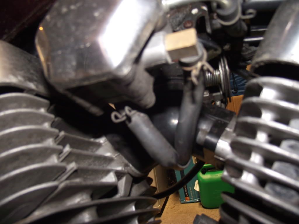
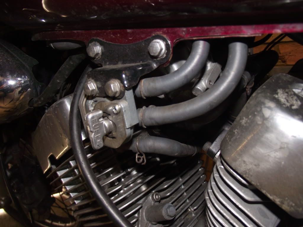
I have managed to work out from the virago diagrams where most of them go but i am stuck on 1 pipe which comes from the carburetor. See photo below
If this is not very clear then it is pipe number 29 on the exploeded diagram here pipe 26
Any help on this would be greatly appreciated as i am really looking forward to getting her back on the road.
Thanks again
Daniel
-
yeah your probably right, i should have placed it in that section.
Good news though, i have checked the exploded diagrams and i have worked out the problem.
just a few other things to sort and then my bike will be on the road.
Thanks for comments
Thank you to everyone who has contributed to the site, there is a lot of knowledge here and it has made it easy for a noob like me to find out what i want.
Keep up the good work.
-
Hello everyone,
Just joined the forum and wanted to say hello and thanks for all the information you guys have up on the site.
Just purchased a virago xv125 so this is my first yamaha. Looking forward to riding it but i have a couple of issues that i thought you guys might be able to help with.
The bike i purchased has a starting problems and i have got most of the parts i need to sort this but the previous owner had taken the fuel tank off and has not replaced the fuel pipes back onto the bike.
Can someone please tell me which pipes should be connected to what on the fuel tap and the pump?
If i look at the fuel tap it has 3 connectors, top middle and bottom. Can anyone tell me which one is supposed to be connected to which pipe.
Sorry to have such a simple question.
Guess thats why i'm a noob
Thanks
Daniel

 )
)


XVS125 carburetor joint
in Yamaha Customs
Posted
Hi All,
I order all my parts from Fowlers motorcycles.
http://www.fowlers.co.uk/
Just give them the yamaha part number and they will have it. If you dont know the number they can help.
Hope it helps